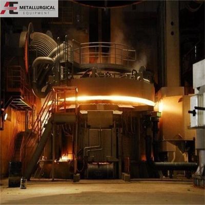
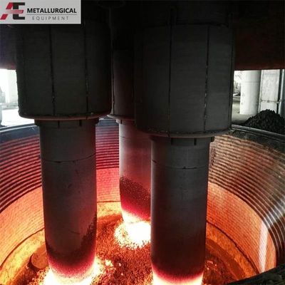
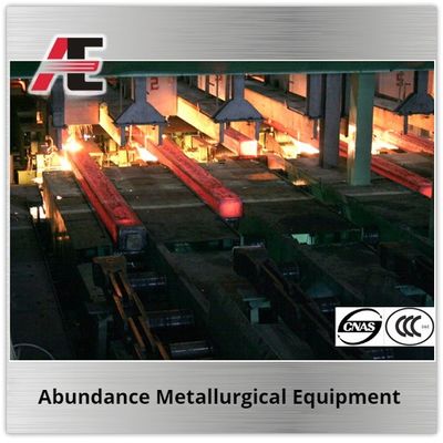
সাবমার্জড আর্ক ফার্নেস (SAF) প্রক্রিয়া
সাবমার্জড আর্ক ফার্নেস প্রক্রিয়াটি একটি ফিডিং সিস্টেম ব্যবহার করে ফার্নেসে কাঁচামাল পর্যায়ক্রমে যোগ করার মাধ্যমে কাজ করে। একটি স্টোকিং মেশিন নিশ্চিত করে যে উপাদানের স্তরটি উপযুক্ত থাকে। গলিত খাদ পর্যায়ক্রমে ফার্নেস থেকে বের করা হয়, যা ল্যাডল বা অন্যান্য পাত্রে প্রবাহিত হয় এবং তারপর ঢালাইয়ের জন্য ছাঁচে পাঠানো হয়। শীতল হওয়ার পরে চূড়ান্ত পণ্যটি আকার নেয়। লোহার স্ল্যাগ একটি ডেডিকেটেড স্ল্যাগ ট্যাপ হোলের মাধ্যমে পর্যায়ক্রমে নির্গত হয়।
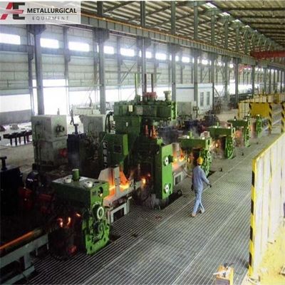
এর প্রধান সরঞ্জামসাবমার্জড আর্ক ফার্নেস
SAF সিস্টেমে বেশ কয়েকটি মূল উপাদান রয়েছে:
ফার্নেস বডি ও আস্তরণ
ফার্নেস কভার
শর্ট নেটওয়ার্ক
জল-শীতলীকরণ ব্যবস্থা
নির্গমন গ্যাস ও ধূলিকণা অপসারণ ব্যবস্থা
বর্জ্য তাপ চিকিত্সা ব্যবস্থা
ইলেক্ট্রোড শেল
ইলেক্ট্রোড হোল্ডিং, স্লিপিং এবং লিফটিং সিস্টেম
চার্জিং ও ডিসচার্জিং সিস্টেম
নিয়ন্ত্রণ ব্যবস্থা
বার্ন-থ্রু ডিভাইস
হাইড্রোলিক সিস্টেম
SAF ট্রান্সফরমার এবং সংশ্লিষ্ট বৈদ্যুতিক সরঞ্জাম

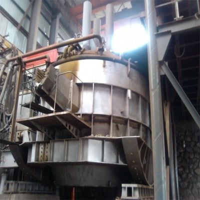
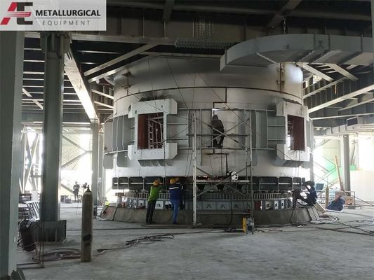
ফার্নেস বডি
ফার্নেস বডি একটি ইস্পাত শেল এবং একটি রিফ্র্যাক্টরি আস্তরণ নিয়ে গঠিত:
ফার্নেস শেল: একটি বটম প্লেট, সাইড প্লেট, রিইনফোর্সিং হুপস এবং রিব প্লেট দিয়ে তৈরি। এটি সাধারণত একটি গোলাকার নকশা যা কংক্রিটে অ্যাঙ্কর করা চ্যানেল স্টিল ফ্রেমওয়ার্ক দ্বারা সমর্থিত পুরু ইস্পাত সাইড প্লেটগুলির সাথে থাকে।
আস্তরণ: উচ্চ-অ্যালুমিনা, ম্যাগনেসিয়া এবং কার্বন-ভিত্তিক রিফ্র্যাক্টরি দিয়ে তৈরি। প্রথম-গ্রেডের ম্যাগনেসিয়া ইট এবং উপকরণগুলি ট্যাপ-হোলের কাছে ব্যবহৃত হয়, প্রায়শই কার্বনেসিয়াস সিলিকা ইটের মতো অন্যান্য রিফ্র্যাক্টরিসের সাথে মিলিত হয়।
শেলের প্রয়োজনীয়তা: আস্তরণের গুরুতর তাপীয় প্রসারণ সহ্য করার জন্য, গরম এবং শীতল চক্রগুলি মিটমাট করার জন্য এবং উপাদান-দক্ষ এবং তৈরিযোগ্য হওয়ার জন্য পর্যাপ্ত শক্তি থাকতে হবে। শেলের মধ্যে একটি সমন্বিত ট্যাপ-হোল অন্তর্ভুক্ত রয়েছে।
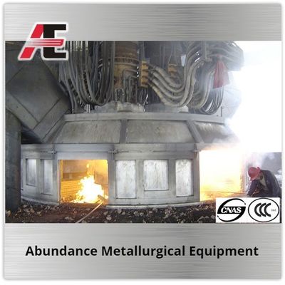
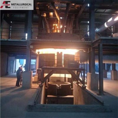
ফার্নেস কভার
বদ্ধ ফার্নেসের কভারটি রিফ্র্যাক্টরি ইট এবং উপকরণ দিয়ে তৈরি করা হয়, জল-শীতল ইস্পাত বিমগুলি এর কঙ্কাল হিসাবে ব্যবহার করে। এতে ইলেক্ট্রোড হোল্ডারগুলির জন্য তিনটি ইলেক্ট্রোড পোর্ট রয়েছে, যা কভার থেকে উত্তাপরোধী। কভারের নীচে ফার্নেস বায়ুমণ্ডলের তাপমাত্রা নিরীক্ষণের জন্য রিফ্র্যাক্টরি ব্রিকওয়ার্কে তাপমাত্রা পরিমাপ সকেটগুলি সুরক্ষা টিউব সহ ইনস্টল করা হয়।
ধোঁয়াশা হুড
হুড ফার্নেস মুখ বন্ধ করে, বিকিরণ তাপ ধারণ করে এবং গন্ধ দূর করে, যা গন্ধ প্রক্রিয়াকরণের সময় উৎপন্ন হয়, যা কর্মপরিবেশ উন্নত করে। এটি একটি ঢালাই করা ইস্পাত কাঠামো (প্রায়শই ষড়ভুজাকার) যা কভার প্লেট, পাশের দেয়াল, দরজা এবং অপারেটিং প্ল্যাটফর্মে অবস্থিত একটি সমর্থনকারী কঙ্কাল নিয়ে গঠিত।
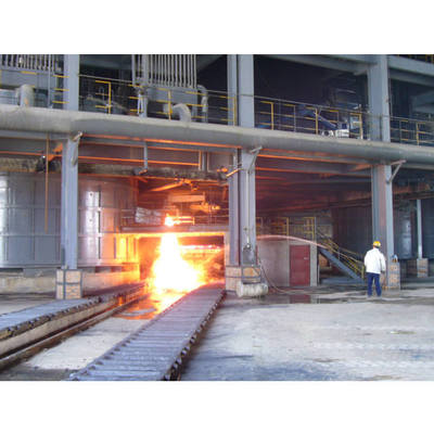
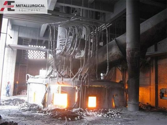
ফ্লু গ্যাস আউটলেট পাইপ
এই সিস্টেমটি হুডের ভিতরে নেতিবাচক চাপ তৈরি করে (প্রাকৃতিক খসড়া বা একটি ফ্যানের মাধ্যমে) যাতে ধোঁয়া বের করা যায়। প্রতিটি ফার্নেসে সাধারণত দুটি ফ্লু থাকে, যা ইস্পাত প্লেট এবং প্রোফাইল দিয়ে তৈরি। একটি ফ্লু অ্যাসেম্বলিতে হুডের উপর স্থাপিত একটি নিম্ন জল-শীতল অংশ, বাইরের দিকে যাওয়া একটি সংযোগকারী পাইপ অংশ এবং ফ্লু খোলার/বন্ধ করার জন্য একটি বেল ভালভ (একটি হাইড্রোলিক সিলিন্ডার দ্বারা পরিচালিত) অন্তর্ভুক্ত থাকে। যখন বন্ধ করা হয়, গ্যাসগুলি ধূলিকণা অপসারণ ব্যবস্থার দিকে পরিচালিত হয়।
ইলেক্ট্রোড হোল্ডার
এটি একটি মূল SAF উপাদান, যা গঠিত:
পরিবাহী ডিভাইস: ঐতিহ্যগতভাবে কারেন্ট বিতরণ এবং সমানকরণের জন্য কালেক্টর রিং, পরিবাহী তামার পাইপ এবং তামার টাইলস (জল-শীতল, লাল তামার ঢালাই) অন্তর্ভুক্ত করে। তামার টাইলস ইলেক্ট্রোডে কারেন্ট প্রেরণ করে।
হোল্ডিং ডিভাইস: তামার টাইলগুলির মাধ্যমে ইলেক্ট্রোড শেলে চাপ প্রয়োগ করে।
স্লিপিং ও লিফটিং ডিভাইস: ইলেক্ট্রোডের দৈর্ঘ্য সমন্বয় এবং অবস্থান করার জন্য ব্যবহৃত হয়।
হোল্ডিং সিলিন্ডার: ইলেক্ট্রোড বাইরের সিলিন্ডার নামেও পরিচিত, এটি হোল্ডার এবং ইলেক্ট্রোডকে স্থগিত করে, উল্লম্ব নড়াচড়ার অনুমতি দেয়।
ইলেক্ট্রোড শেল: ইলেক্ট্রোড পেস্ট ধারণ করে, যা ব্যবহারযোগ্য ইলেক্ট্রোড তৈরি করতে সিন্টার করে।
তামার টাইল-থেকে-ইলেক্ট্রোড যোগাযোগের চাপ সাধারণত 0.05–0.15 MPa। ইলেক্ট্রোড সিন্টারিং জোন শক্তির জন্য একটি গুরুত্বপূর্ণ এলাকা।
ইলেক্ট্রোড লিফটিং ডিভাইস
এই ডিভাইসটি সার্কিট প্রতিরোধ ক্ষমতা এবং কারেন্ট নিয়ন্ত্রণ করতে ইলেক্ট্রোড আর্ক দৈর্ঘ্য সমন্বয় করে। লিফটিং গতি ফার্নেস পাওয়ার এবং ইলেক্ট্রোডের ব্যাসের সাথে পরিবর্তিত হয় (যেমন, ব্যাস >1m এর জন্য 0.2–0.5 m/min)। সাধারণ লিফটিং স্ট্রোক হল 2.1–2.6 মিটার।
শর্ট নেটওয়ার্ক সিস্টেম
শর্ট নেটওয়ার্ক ট্রান্সফরমার থেকে ইলেক্ট্রোডে নিম্ন-ভোল্টেজ, উচ্চ-কারেন্ট পাওয়ার প্রেরণ করে। এর নকশা বৈদ্যুতিক দক্ষতা এবং অ-লৌহঘটিত ধাতুর ব্যবহার কমানোর জন্য গুরুত্বপূর্ণ। মূল প্রয়োজনীয়তা হল:
পর্যাপ্ত কারেন্ট-বহন ক্ষমতা।
ন্যূনতম প্রতিরোধ ক্ষমতা।
কম ইন্ডাকটিভ রিঅ্যাক্টেন্স।
পর্যাপ্ত নিরোধক এবং যান্ত্রিক শক্তি।
শর্ট নেটওয়ার্ক ক্ষতিপূরণ
শর্ট নেটওয়ার্ক সিস্টেমের প্রায় 70% রিঅ্যাক্টেন্সের অবদান রাখে, যার ফলে একটি কম প্রাকৃতিক পাওয়ার ফ্যাক্টর (প্রায়শই 0.7–0.8) হয়। এটি ট্রান্সফরমারের দক্ষতা হ্রাস করে, শক্তি নষ্ট করে এবং ইউটিলিটি জরিমানা হতে পারে। ক্ষতিপূরণ (পাওয়ার ফ্যাক্টর সংশোধন এবং ফেজ ব্যালেন্সিং) বাস্তবায়ন শক্তি খরচ কমাতে এবং গন্ধ প্রক্রিয়াকরণের দক্ষতা উন্নত করার একটি কার্যকর উপায়।
উচ্চ-ভোল্টেজ পাওয়ার সাপ্লাই সিস্টেম
এই সিস্টেমে উচ্চ-ভোল্টেজ আইসোলেটর, ভোল্টেজ/কারেন্ট ট্রান্সফরমার এবং ভ্যাকুয়াম সার্কিট ব্রেকার অন্তর্ভুক্ত রয়েছে। এটি নিরাপত্তা এবং অপারেশনাল নিয়ন্ত্রণ বজায় রেখে ফার্নেসে নির্ভরযোগ্য বিদ্যুৎ সরবরাহ নিশ্চিত করে।
আমরা একটি পেশাদারবৈদ্যুতিক ফার্নেস প্রস্তুতকারক। আরও বিস্তারিত তথ্য এবং প্রযুক্তিগত সহায়তার জন্য, অনুগ্রহ করে আমাদের বিক্রয় প্রকৌশলী-এর সাথে যোগাযোগ করুনsusan@aeaxa.com।

 আপনার বার্তাটি 20-3,000 টির মধ্যে হতে হবে!